|
|
|
|
|
|
LX90 Pinouts
|
Following are diagrams for the pinout connections
on a number of LX90 ports
All diagrams are shown with the locking tab facing down, cables
should be viewed accordingly
|
|
|
|
|
|
Cable diagrams
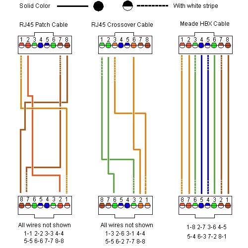
You can see from
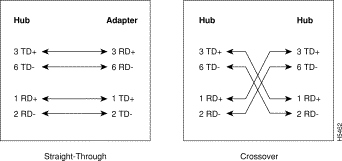
these diagrams why you shouldn't try to use a network "crossover"
or "uplink" cable with your LX90 Autostar. It's also
apparent that you shouldn't use a CAT5 patch cable alone as well.
If you must extend your HBX cable, use a straight through female-female coupler on your HBX cable, then add a standard
CAT5 patch cable and plug that into your Autostar. A "straight
through" F-F coupler is wired the same as a CAT5 patch
cable, maintaining the pin to pin connections through the coupler.

10baseT cable wiring
The other alternative is to make your own cable from scratch. This keeps the wiring of the complete assembly proper. Improper cableing can result in a blown Autostar - know what you're doing ahead of time and use a VOM to check your connections. Do NOT go by color alone, your ultimate goal is to have the pin to pin connections at each end correct, not the colors. Note the position of the locking tabs on either end of the cables.

All wires were not
drawn on the CAT5 cables, to preserve some clarity. The colored
pins at each connector end notate the wiring, as does the
numbered pin connections below the drawing. Also, note that the
colors on the Meade HBX cable are only for reference to the 100baseT
network cables. Meade may use different wire at times, and colors
may not match. The colors used are the standard eight CAT5
cabling colors of orange, orange/white, green, green/white, blue,
blue/white, and brown, brown/white.
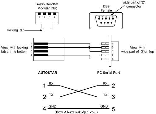
RS232 cable wiring (Meade #505 equivalent)

Bolt , thread and wrench sizes (LX90)
Main Tripod bolt.....................................1/2-13
x 8 1/4" (threads only)
Collimation screws............................... 6-32x3/8"...5/64"
allen wrench
Fork Cover screws.................................................3/32"
allen wrench
Tripod adapter (base).............................................3/32"
allen wrench
Base inspection cover screws................................. .050
allen wrench
Tripod head (6 wedge holes) ....................................
5/16-18 (coarse)
Azimuth adjuster holes (tripod)...................................................
8-32
OTA accessory screws........................................................8-32x1/2
Tripod adjustable leg locking bolts................................1/4-20
(coarse)
Focuser set screws..........................................................5/64"
allen
Focuser flange.................................................................5/64"
allen
Finderscope dovetail thumbscrews...................................1/4-20
x 3/4
Finderscope collimation thumbscrews...............................10-32
x 3/4
SCT rear port....................................................................2"
x 24 tpi
Visual Back external threads......................................1.375" x
24 tpi

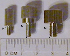
Common metric thumbscrews used on
telescopes
Typical metric thumbscrews used on diagonals, barlows and visual backs are M2 (0.4 pitch), M3 (0.5 pitch) and M5 (0.8 pitch)
At the time this document was written, this information was up to
date and correct, however companies change designs and wiring of
circuit boards on a regular basis. It's strongly recomended that
you check your scope first hand before making wiring decisions
based upon these diagrams.
|| Back
to Contents || Wedge
adapter || Focuser
|| Azimuth
adjuster || Weight
Set || Dovetail
||
|| Compass
|| Polar
|| Pinouts
|| Tours/Ephemerides
|| LED
Markers || Balance
|| Focuser
Bearings ||
|| Corrector || Encoders
|| Firmware ||